|
I am no longer maintaining the electronics sections of this site. For an explanation, see the electronics contact page. If you need help, you can ask your question in The Forum. |
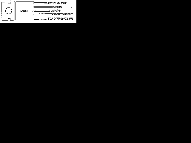
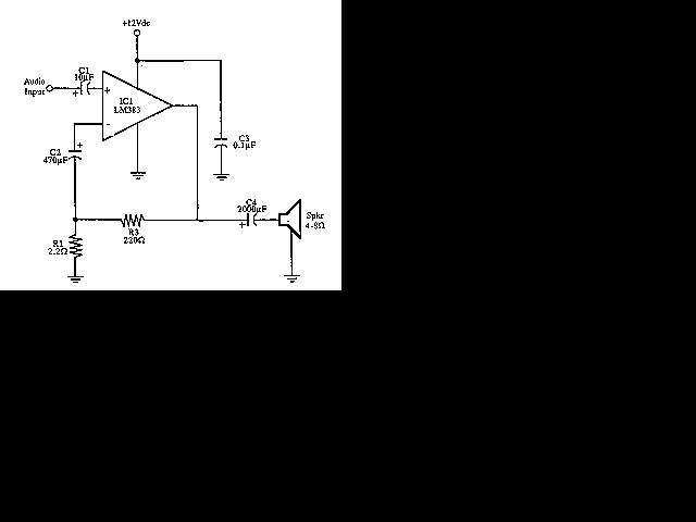
Here is the schematic for an 8 watt audio amp. This amp can be used as a simple booster, the heart of a more complicated amplifier or used as a guitar amp.


| C1 | 1 | 10uf Electrolytic Capacitor | |
| C2 | 1 | 470uf Electrolytic Capacitor | |
| C3 | 1 | 0.1uF Disc Capacitor | |
| C4 | 1 | 2000uf Electrolytic Capacitor | 2200uF |
| R1 | 1 | 2.2 Ohm Resistor | Anything Within 10% |
| R2 | 1 | 220 Ohm Resistor | Anything Within 10% |
| IC1 | 1 | LM383 8 Watt Amp IC | ECG1232 |
1. IC1 MUST be installed on a heat sink.
2. C3 is for filtering and to prevent oscillation and should not be omitted.
3. The circuit can be built on a perf board, universal solder board or PC board, the PC board is preferred. I built the circuit on a perf board and had to add extra inductors, capacitors and resistors to prevent oscillation.
4. The circuit draws about 880 ma at 12 V.
5. By swapping the values of R1 and R3, you can turn this amplifier into a guitar amp with no preamp required.
6. If you can't find 2000uF, then replace C4 with a 2200uF unit.
7. If you add a 0.2uF capaciitor in series with a 1 ohm resistor to the output you can prevent oscillation of the circuit under certain conditions.