|
I am no longer maintaining the electronics sections of this site. For an explanation, see the electronics contact page. If you need help, you can ask your question in The Forum. |
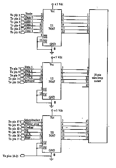
This is the basic interface I used as part of my Computerized Room project. This is the parallel interface only. The 8 bit input card can be found, along with the rest of the project, at Computerize Your Room/House. This interface, as well as the other two interfaces, came from the book "The Robot Builders Bonanza", by Gordan McComb. This interface is also useful for controlling small robots, etc. It is cheap and fairly easy to build, although you should not attempt this project unless you have prior experience with electronics. You probably won't damage anything if you hook it up wrong, but there is always a chance (some parallel ports are better protected then others). If possible, test the project on someone else's, or a school computer :-)


| U1, U2, U3 | 3 | 74LS367 Buffer IC | 74367, 74HC367 |
| MISC | 1 | Case, Wire, Sockests, 18 Pin Socket (For Output), 25 Pin Connector (For Parallel Port), Ribben Cable |
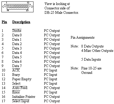
1. I built the interface on a piece of universal solder board due to the large number of wires that must cross. It is also much easier to fix mistakes then on a PC board. I also used a 25 pin crimp connector to connect it to the parallel port. 26 conductor ribben cable was used to link the connector to the board.
2. This interface only offers 5 inputs (on some computers it may be less). For more inputs, see Computerize Your Room/House. If you choose to use the inputs, remember that the voltage level can not exceed 5 volts or fall below ground.
3. This circuit is TTL and therefor MUST be powered by no more then 5 volts.
4. You can download control software from my files section.
5. For more information on programming the parallel port, see Programming The Parallel Port In QBasic or Programming The Parallel Port In Visual Basic.