

|
I am no longer maintaining the electronics sections of this site. For an explanation, see the electronics contact page. If you need help, you can ask your question in The Forum. |
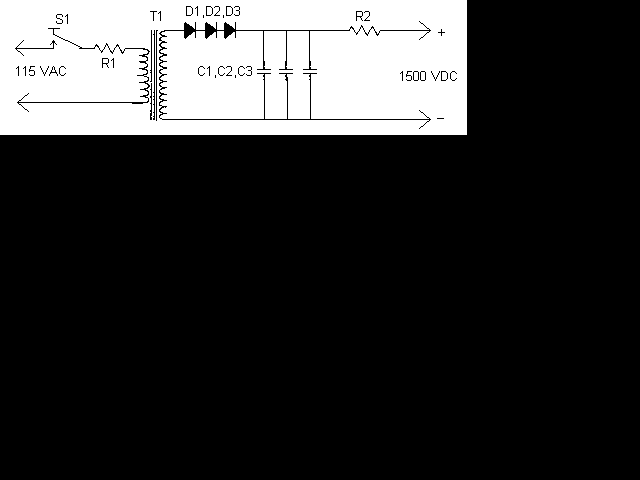
If you have ever worked with lasers, you know how fun and interesting it can be, you also know how expensive it can be. The high voltage power supplies for the laser tubes are often more expensive then the tubes themselves. This supply can be built with commmon parts, most of which you probably already have in your junk box. The secret is the transformer used. It is a common 9V 1A unit, connected backwards for step up.
Please note that some people may have trouble with this supply. This is due to the slight difference in transformers. For more information on LASER power supplies, take a look at Sam Goldwasser's Laser Supply Info Page.


| R1 | 1 | 10 Ohm 10W Or Greater Resistor | |
| R2 | 1 | Ballast Resistor, See "Notes" | |
| D1, D2, D3 | 3 | 1N4007 Silicon Diode | |
| C1, C2, C3 | 3 | 0.1 uF 2000V Capacitor | |
| T1 | 1 | 9V 1A Transformer | |
| S1 | 1 | 115V 2A SPST Switch | |
| MISC | 1 | Case, Wire, Binding Posts (for output), Line Cord |
1. T1 is an ordinary 9V 1A transformer connected backwards for step up.
2. R1 MUST be installed on a LARGE heatsink. A good heatsink is the metal case the supply is built in.
3. R2 Protects the laser tube from excess current. It should be soldered directly to the anode terminal on the tube. To find R2, start with a 500K 10W resistor and work down until the tube lights and remains stable.
4. If you have trouble with the tube not starting easily, use a longer anode lead that is wrapped around the tube.
5. Depending on the transformer you use, the circuit may or may not work. I cannot guarantee the operation of this circuit. Build at your own risk.