|
I am no longer maintaining the electronics sections of this site. For an explanation, see the electronics contact page. If you need help, you can ask your question in The Forum. |
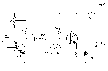
Flash slaves are used when you need to supplement one flash unit with one or several more. This slave trigger simply triggers those other units. It does this by "seeing" the first flash (using a phototransistor) and triggering the other flashes a few microseconds later. The sensitivity of the circuit is adjustable to compensate for ambient light or dimmer than usual master flashes.
| R1 | 1 | 47K Linear Pot | |
| R2, R3 | 2 | 3K 1/4W Resistor | |
| R4 | 1 | 220 Ohm 1/4W Resistor | |
| C1 | 1 | 10uf 25V Electrolytic Capacitor | |
| C2 | 1 | 0.047uf 25V Ceramic Capacitor | |
| Q1 | 1 | 2N5777 NPN Darlington Phototransistor | |
| Q2, Q3 | 2 | 2N3904 NPN Transistor | 2N2222 |
| SCR1 | 1 | 400V 2A SCR | |
| S1 | 1 | 1A 120V SPST Switch | |
| P1 | 1 | Plug to match jack on slave flash | |
| MISC | 1 | Knob For R1, Wire, Board |
1. Q1 should be aimed at the master flash. R1 should be adjusted for maximum sensitivity but no false triggering.
2. Keep your fingers away from SCR1 when the circuit is operating. It is at 50V-300V and will give you a nasty shock.