
|
I am no longer maintaining the electronics sections of this site. For an explanation, see the electronics contact page. If you need help, you can ask your question in The Forum. |
This Adjustable Strobe Light is the bigger brother of the plain old strobe light. This one uses a much more powerful "horse shoe" Xenon tube which produces more light. You can also control the flash rate up to about 20Hz. Do not look directly at the flash tube when this thing is on!
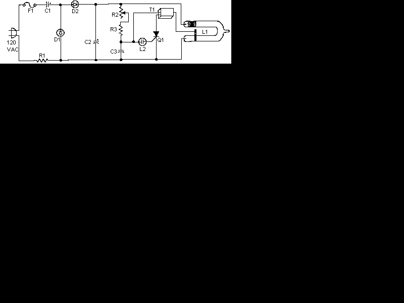
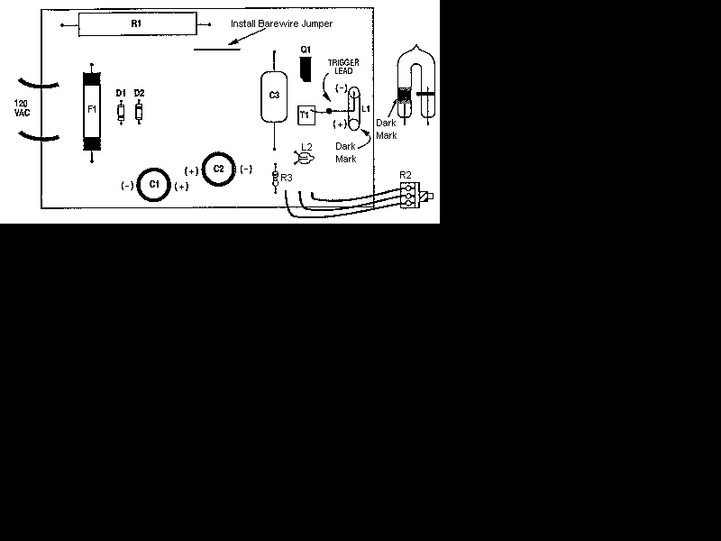
| R1 | 1 | 250 Ohm 10 Watt Resistor | |
| R2 | 1 | 500K Pot | |
| R3 | 1 | 680K 1/4 Watt Resistor | |
| D1, D2 | 2 | 1N4004 Silicon Diode | |
| C1, C2 | 2 | 22 uF 350V Capacitor | |
| C3 | 1 | 0.47uF 400 Volt Mylar Capacitor | |
| T1 | 1 | 4KV Trigger Transformer (see "Notes") | |
| L1 | 1 | Flash Tube (see "Notes") | |
| L2 | 1 | Neon Bulb | |
| Q1 | 1 | 106 SCR | |
| F1 | 1 | 115V 1A Fuse | |
| MISC | 1 | Case, Wire, Line Cord, Knob For R2 |
1. T1 and L1 are available from The Electronics Goldmine (see Where To Get Parts).
2. This ciruits is NOT isolated from ground. Use caution when operating without a case. A case is required for normal operation. Do not touch any part of the circuit with the case open or not installed.
3. Most any diodes rated at greater then 250 volts at 1 amp can be used instead of the 1N4004's.
4. Do not operate this circuit at high flash rates for more than about 30 seconds or else C1 and C2 will overheat and explode.
5. There is no on/off switch in the schematic, but you can of course add one.