|
I am no longer maintaining the electronics sections of this site. For an explanation, see the electronics contact page. If you need help, you can ask your question in The Forum. |
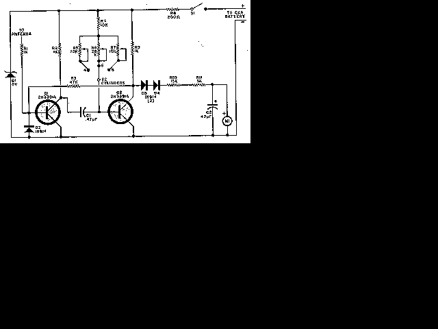
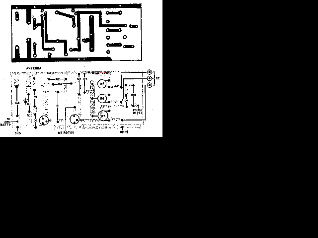
Anyone performing their own automobile tune-ups knows how important it is to know your engines speed. With this tachometer, you can measure your engines speed without any connections or annoying timing lights.


| C1 | 1 | 0.47uF Capacitor | |
| C2 | 1 | 47uF Electrolytic Capacitor | |
| D1 | 1 | 8V 1W Zener Diode | |
| D2, D3, D4 | 3 | 1N914 Diode | |
| M1 | 1 | 200uA Meter | |
| Q1, Q2 | 2 | 2N3391A Transistor | |
| R1, R2, R9 | 3 | 1K 1/2 W Resistor | |
| R3 | 1 | 47K 1/2 W Resistor | |
| R4 | 1 | 10K 1/2 W Resistor | |
| R5, R6 | 2 | 25K Trim Pot | |
| R7 | 1 | 10K Trim Pot | |
| R8 | 1 | 200 Ohm 2 W Resistor | |
| R10 | 1 | 15K 1/2 W Resistor | |
| R11 | 1 | 2.2K 1/2 W Resistor | |
| S1 | 1 | SPST Togglae Switch | |
| S2 | 1 | Three Position Single Pole Rotary Switch | |
| MISC | 1 | Telescoping Radio Antenna, Enclosure, Power Cable and Battery Connector |
1. Calibrate the unit as folows:
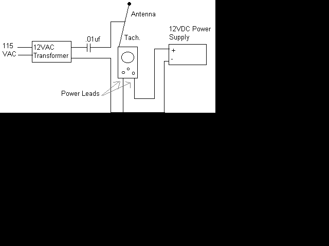
a. Set up this circuit:
b. Turn on the Tach and allow a few minutes for temperature stabilization.
c. Set S2 to 4 cylinders and adjust R5 for a meter indication of 180 (1800 rpm).
d. Set S2 to 6 cylinders and adjust R6 for a meter indication of 120 (1200 rpm).
e. Set S2 to 8 cylinders and adjust R7 for a meter indication of 90 (900 rpm).
2. To use the Tach, turn it on and let it sit for one minute to allow for temperature stabilization. Extend the antenna, select the right number of cylinders and hold the unit over the engine. If the reading is erratic or the needle jumps around, move the antenna closer to the ignition coil or spark plug wires.
3. The unit draws power from the car battery. If it is connected backwards, it will not work, but it won't be damaged.