|
I am no longer maintaining the electronics sections of this site. For an explanation, see the electronics contact page. If you need help, you can ask your question in The Forum. |

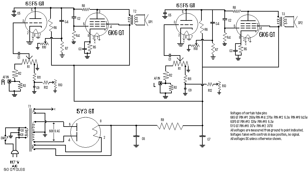
| R1, R10, R13 | 6 | 2.2Meg Pot | |
| R2 | 2 | 470K 1/2W Resistor | |
| R3 | 2 | 1 Meg 1/2W Resistor | |
| R4 | 2 | 220K 1/2W Resistor | |
| R5 | 2 | 330 Ohm 2W Resistor | |
| R6 | 2 | 220K 1/2W Resistor | |
| R7 | 2 | 2.2Meg 1/2W Resistor | |
| R8 | 2 | 1Meg 1/2W Resistor | |
| R9 | 1 | 720 Ohm 20W Resistor | |
| R11 | 2 | 33K 1/2W Resistor | |
| R12 | 2 | 22K 1/2W Resistor | |
| C1, C9 | 4 | 0.005uF 400V Capacitor | |
| C2 | 2 | 0.05uF 600V Capacitor | |
| C3 | 2 | 20uF 25V Electrolytic Capacitor | |
| C4 | 2 | 0.01uF 400V Capacitor | |
| C5 | 2 | 200uuF 400V Ceramic Disc Capacitor | |
| C6, C7 | 2 | 15uF 450V Capacitor | |
| C8 | 2 | 15uF 400V Capacitor | |
| T1 | 1 | 117V Primary, 350VCT Secondary, 6.3V Secondary, 6.3V Secondary | |
| T2 | 2 | 7600 Ohm Primary, 4 or 8 Ohm Secondary | |
| SW1 | 1 | SPST Switch | |
| SP1, SP2 | 2 | 12" or smaller, 4 or 8 ohm speakers | |
| MISC | 1 | 5 tube sockets, 2 RCA jacks, PC board or chassis, wire, knobs, etc. |
1. Email Weslee Kinsler with questions, comments, etc.
2. The 6V6 GT tube may be substituted for the 6K6 to lower power requirements.
3. C8 is for radio interference suppression and may be omitted.
4. The 5Y3 GT tube should be mounted in a vertical position and be well ventilated. The 6K6 and 6SF5 tubes can be mounted in any position.
5. Controls should have an audio taper.
6. The power supply portion of this unit may be used for anything requiring 290-320v DC up to about 3 amps. >p>7. The author has provided a link to an updated version of this circuit. The newer revision contains parts changes based on the author's tinkering and experience with the circuit over the past few years.